Place: Halle
Tanks flown: 2
Time flown: 1h01 (cumulative model timer: 24h20) (including a lot of setup-time for the governor)
Rx battery recharged with: 268+1472 mAh (same behavior as some weeks ago)
Tx battery recharged with: 554 mAh
Glow heater battery recharged with: 439 mAh
Starter battery recharged with: 141 mAh
Comment:
I just bought myself a governor and needed to test it out. Besides that, a fairly calm day at the field. Besides testing out the governor, I continued to exercise my figure-8’s and nose-in hoover. After the last flight, I noticed that the rotor wasn’t rotating as freely as it used to.
When investigating this at home, the tail rotor made a slight rubbing sound:
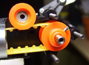
The locking pin to keep the tail rotor shaft in place came out of its place. Pushing it back and re-tightening the set screw solved this problem.
Also, I basically undid the tracking adjustment: “black” was too high, so I decreased its pitch by 1 turn.
The governor
A governor is a device that stabilizes the rotor speed using a feedback mechanism. The Futaba GV-1 uses a Hall sensor to detect the magnets attached to the engine-fan. Here is the report about the device itself, its installation and the first test results.
From the 2 flights I did with the governor, I’m fairly happy with it. It does what I want it to do: govern the throttle to keep constant RPM. I must admit that I don’t (yet) do very demanding maneuvers…
The mechanics
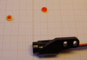
The tiny magnets (shown below) are 4.0mm in diameter and 1.5mm in height. The sensor reacts only to one of their poles, which I marked with a red marker. The magnets mass is around 157mg (the left one weighs 156.8mg, the right one 157.2mg).
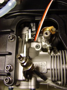
The standard fan of the Raptor has two spots to mount the magnets pre-made:
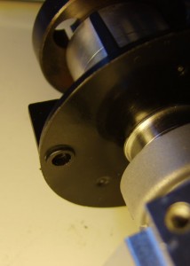
The GV-1 needs 1 impulse per revolution, so only one magnet needs to be installed. However, the fan rotates at fairly high speeds (my normal engine, and thus fan, speed is around 15000rpm) which generates a lot of centrifugal force: The magnets are mounted 23mm from the center of rotation, which results in a centrifugal force:
F = m.r.ω² = 157E-6 kg . 23E-3 m . (15000/60*2*pi)² rad²/sec² = 8.9 N
This is the equivalent of 0.91 kg in the earth’s gravitation.
This unbalance will cause the fan to vibrate heavily. Therefor, the second magnet can be mounted on the opposite side of the fan, thereby rebalancing the fan. To keep the sensor happy, this second magnet should be mounted “upside-down” so it does not trigger the sensor.
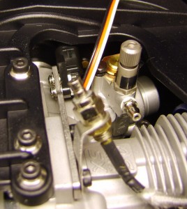
Mounting the sensor to the engine is done using one of the three stays (one for .30 size engines, one for .50 size engines and one for .60 size engises). The stay fits on the engine in both directions (jumping away or towards the engine), but the frame of the Raptor is just a little to small to use the “away” position. To get an optimal signal, I had to mount the sensor a bit rotated to the “outside”.
The electronics
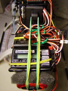
The GV-1 needs to be inserted BETWEEN the receiver and the throttle servo. When it is inactive, the received throttle-commands are just passed on to the servo. When engaged, the received throttle-command is mostly ignored and the feedback mechanism controls the throttle.
The GV-1 has 3 inputs: The already mentioned throttle, the rpm-selection and the on/off/mixture channel. The rpm-selection does just that: selecting the rpm to aim for. This is basically a 3-point curve. When using a switch to select, you will only hit the configured points. When using an analog input (dial or slider) you can actually use the complete curve. (According to the manual, I haven’t checked it.)
The on/off/mixture channel can be used to turn on/off the governor. Switching the governor on/off can also be done using the rpm-selection channel (by setting 1 point to 990rpm which equals off) or the throttle-channel (throttle below 15% turns off the governor). This third channel can also be used to control the mixture of the engine. Since the governor takes over the throttle-command, it needs to adjust the mixture as well.
The outputs are obviously the (governed) throttle and mixture. The top connection is for the sensor.
The settings
The GV-1 has a list of settings you can adjust. Adjustments need to be done on the unit itself using very small buttons. I found it easiest to use the micro screwdriver that came with the unit to push the buttons.
Here is an overview of the settings I configured:
- rS0 – rpm position 0% – off
- rS1 – rpm position 50% – 1650rpm
- rS2 – rpm position 100% – 1700rpm
- Disp – Display which rpm (rotor or engine) – Rot
- GRt – Gear ratio – 8.5
- SWPt – Invert the on/off/mixure channer – On (so the “empty” input is interpreted as On)
- SWSt – Switch on/off based on throttle – INH (inhibit, ignore throttle)
- GvOf – Override governor when >xx% throttle – INH (don’t override)
- MxMD – Mixture servo mode – Gov
- MGx – 9-point-curve for mixture servo – defaults
- ATV – End-points for mixture servo – defaults
- MSx – Mixture servo reverse – default
- MTrm – Mixture trim – default
- B/FS – Battery FailSafe – ACT (activate when battery drops below 3.8V)
- B/FD – Battery FailSafe position – 4% (little bit above idle in my setup)
- Lmt – Limits of the throttle servo – as set on the Tx
The settings – transmitter side
The transmitter needs to be adapted as well. I chose to use my Idle-Up modes to control my governor. All my Idle-Ups have the same -9°:+9° pitch range, so it made sense to use the different modes for different head-speeds. IdleUp3 is on a different switch and only used for testing; it just uses the governor settings from the Normal/IdleUp1/IdleUp2 switch. ThrottleHold knows how to override the governor to the off position.
| Stick | Normal | IdleUp 1 | IdleUp 2 | IdleUp 3 | ThrHold | |||||
|---|---|---|---|---|---|---|---|---|---|---|
| Pitch | Throttle | Pitch | Throttle | Pitch | Throttle | Pitch | Throttle | Pitch | Throttle | |
| 0% | 38.0% | 0.0% | 12.5% | 10% | INH | INH | 10.5% | 0% | ||
| 25% | 44.0% | 14.0% | 32.0% | 22.5% | 30.0% | |||||
| 50% | 50.0% | 22.5% | 50.0% | 28.0% | 50.0% | |||||
| 75% | 65.0% | 36.0% | 65.0% | 36.0% | 65.5% | |||||
| 100% | 80.0% | 57.5% | 82.5% | 57.5% | 100.0% | |||||
| Governor | Off | 1650 | 1700 | N/A | Off (override) | |||||
Just for the record, here are all the settings:
- D/R,EXP
- AILE
- Switch: D
- Up
- D/R: 100%
- EXP: -15%
- Down
- D/R: 100%
- EXP: 0%
- ELEV
- Switch: D
- Up
- D/R: 100%
- EXP: -15%
- Down
- D/R: 100%
- EXP: 0%
- RUDD
- Switch: D
- Up
- D/R: 100%
- EXP: 0%
- Down
- D/R: 100%
- EXP: 0%
- AILE
- END POINT
- AIL: 62/62
- ELE: 72/72
- THR: 80/75
- RUD: 100/100
- GYR: 100/100
- PIT: 89/77
- AU1: 100/100
- AU2: 100/100
- SUB-TRIM
- AIL: 0
- ELE: +2
- THR: 0
- RUD: 0
- GYR: 0
- PIT: -16
- AU1: 0
- AU2: 0
- REVERSE
- AIL: Rev
- ELE: Nor
- THR: Rev
- RUD: Rev
- GYR: Nor
- PIT: Nor
- AU1: Nor
- Au2: Nor
- TRIM
- AILE: > 8
- ELEV: v 8
- THRO: ^ 16
- RUDD: > 20
- THR-CUT
- MIX: OFF
- RATE: -15%
- THR: 5%
- SW: H
- POSI: DOWN
- F/S
- AIL: F/S 0%
- ELE: F/S 0%
- THR: F/S 25%
- RUD: F/S -3%
- GYR: F/S -71%
- PIT: F/S -13%
- AU1: F/S +99%
- AU2: NOR
- AUX-CH
- CH5: Sw-B
- CH7: Sw-C
- CH8: Sw-C
- CH9: Sw-A, REV
- PARAMETER
- TYPE: HELI (SWH1)
- MODUL: PCM
- ATL: ON
- TIMER
- <1>
- TIME: 10:00
- MODE: UP
- SW: STk-THR
- POSI: 5%
- <2>
- TIME: 10:00
- MODE:DOWN
- SW: STk-THR
- POSI: 10%
- <3>
- MODE: MODEL
- <1>
- TRAINER
- INH
- THR-CURVE: see above
- PIT-CURVE: see above
- REVO MIX: INH
- GYRO SENS
- MODE: GY
- MIX: ACT
- RATE-UP: AVC 85%
- RATE-DOWN: NOR 85%
- SW: B
- HOV-THR: INH
- HOV-PIT: INH
- HI/LO-PIT: MAN (disabled)
- THR-HOLD: see above
- RUD-OFST: INH
- OFFSET: INH
- DELAY: 0% everywhere
- GOVERNOR
- RATE-UP: 0.0%
- RATE-CNTR: 50.0%
- RATE-DOWN: 100.0%
- SW: E
- MIX: ACT
- CUT-CH: CH7
- DIR: +Limit
- THR->NEEDL: INH
- SWASH->THR: INH
- SW SELECT
- IDL1/2: E
- IDLE3: F
- T-HOLD: G
- PROG MIX 1: INH
- PROG MIX 2: INH
- PMIX6 CURVE: INH
