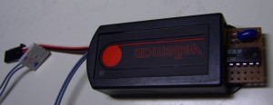
A few months ago, I got the FlyCamOne2 as an add-on for my Raptor. The manual mentions that the recording can be started and stopped electronically. With some additional electronics, it should be possible to start/stop the camera from the ground using one of the free channels on my remote.
The free channel can’t be used directly: the receiver sends out pulses of different lengths (between 1ms and 2ms), while the FlyCamOne2 needs a simple short to start recording. Some electronics will be needed to convert between these two.
After some googling, I found the CurveRC FCO2 I/F which does exactly that. But there are some downsides:
- It consumes a lot of power (10mA on 5V)
- Isn’t cheap (£10, plus international shipping, at the time of this post)
- I don’t get to enjoy myself figuring out how to do this myself
The CurveRC print seems to be build around an Atmel Tiny25 microcontroller, which is an 8bit RISC processor with 2K of build-in flash. Using a microprocessor makes the design fairly simple since nearly everything can be done in software. However, it must be clocked at reasonable speed to do something useful. This explains the fairly high power consumption.
So I decided I could do “better”.
Measurements
First some measurements on the output signal of the receiver:
- Even though the Rx is powered at around 5Vdc, the pulses are only 3V high
- The pulse is repeated every 15ms (i.e. 66.6Hz)
- The pulse width is between 1ms and 2ms, depending on the value of the channel. Center-stick results in a 1.5ms pulse. The digital channel (number 9 on my R319DPS) only outputs one of both extremes.
The FlyCamOne2 manual only specifies that pins 1 and 2 should be shorted. I needed a bit more info, so I had to measure it myself:
- Pin2 – Pin1 has 2.7V open-circuit voltage
- Shorting them results in 310µA of current
Design
After these measurements, I had enough information to start designing. Important things where low power usage and small form-factor; so I tried to use only a single IC to do the job.
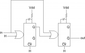
The result is shown below. It uses a 4528 IC which contains 2 monostable retriggerable multivibrators. By using both the non-inverted and inverted input of the second one-shot, I was able to get the job done. I used the Philips (now NXS) HEF4528BP (local copy) variant of the HEF4000 (local copy) family.
The first single-shot is triggered by every leading edge of the input signal (i.e. on the start of every pulse). The resistor and capacitor on top are chosen to give a 1.5ms output pulse: 39kΩ and 94nF (2x 47nF). (In practice my output pulse is more like 1.3ms.)
When this output-pulse is inverted and ORed with the input, the result is a negative pulse when the input is shorter than 1.5ms; or no pulse when the input is longer than 1.5ms. This is shown below:
The second one-shot has an RC time-constant of somewhat more than 15ms. I used 120kΩ and 470nF. This pulse should be long enough so it the next input-pulse can retrigger it. The dotted lines in the output indicate the point where it is retriggered and the point where it would have ended.
Input and output signals
The designed circuit is completely digital, but the world is analog. And this causes some problems:
- The input signal is only 3V high; the 4528 needs 3.5V to understand “high” when powered at 5V.
- The output is 0V when “low” and Vdd when “high”; the FlyCamOne2 needs a short.
The input was easy. The 4528 was happy with the 3V it got from the receiver and worked without any modification.
The output in its “low” state is able to sink around 440µA (typical value at 5V Vdd), which is enough to “short” the FlyCamOne2’s inputs. All I need to do is connect pin 1 of the FlyCamOne2 to the ground in the circuit, and connect pin 2 to the output.
The output in its “high” state will try to pull the 2.7V OCP up to its Vdd (around 5V). The result is a 3mA current and 4V. A simple Silicon diode solved this problem.
During these tests, I also concluded that the documentation of the FlyCamOne2 is incomplete:
- When the FCO2 is powered up with its pin 2 floating, shortening it to pin 1 does result in a recording (as documented)
- When the FCO2 is powered up with its pin 2 shorted to 1, RELEASING pin 2 starts a recording; the exact opposite of the documented behaviour.
Note-to-self: always power up the Rx before the FCO2.
The result
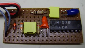
The top 3 components are the smoothening of the power supply: an 100Ω resistor, followed by a 10µF and 47nF capacitor.
On the far left is the diode, followed by the RC for the short one-shot; followed by the RC for the long one-shot. The 4528 is obviously on the right.
Using a test signal containing short (1ms) pulses and long (2ms) pulses, the output was behaving as expected. The whole circuit (including RC circuits) used around 5µA when doing nothing. When long pulses (2ms) are applied to the input, the power consumption is around 60µA. Short pulses (1ms) use around 400µA, since the second one-shot needs to be reloaded every time.


